|
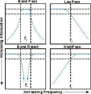
CMC Filters are available in
bandpass, lowpass, band reject and highpass designs. When
specifying your filter needs, be sure to supply all pertinent
information. To achieve the best results, additional
specifications such as phase, group delay, power, size, and
mechanical requirements should be supplied. Many styles of CMC
filters are available in tunable as well as fixed tuned
versions. The engineering staff at CMC will be happy to advise
you in filter styles to best meet your specific combination of
bandwidth, loss, selectivity, size, power handling etc.
WAVEGUIDE
Waveguide filters consist of half wavelength resonant cavities coupled by capacitive or inductive irises. Low percentage bandwidths are best realized in cylindrical resonators. Very high Q factors and tuneability are attractive features of this style. Rectangular resonators are better suited to wider percentage bandwidths and offer high Q, very high selectivity, and lower cost.
COAXIAL
Coax units consist of quarter wavelength resonant stubs coupled by capacitive or inductive irises. Typical bandwidths range between 0.5 and 2.0%. This style resonator lends itself well to broad tuning ranges or is very economical in fixed versions. Q factors are relatively high and selectivity associated with up to 8 sections is available in tunable versions.
COMBLINE
Combline design utilizes distributed inductances and lumped capacitances. Bandwidths up to 30% are realizable. Q factors are relatively high and can be traded against very small package sizes.
INTERDIGITAL
Interdigital design distributes both
inductances and capacitances in an array of short circuit
quarter wavelength lines. Bandwidths up to 100% can be
obtained. Q factors are high and can be traded against smaller
package sizes.

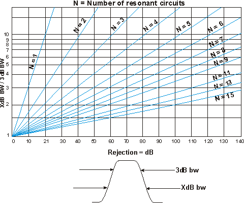
To determine the number of resonant
sections which are necessary to meet your particular
specifications, simply divide the 3db bw into the bandwidth
required to meet the rejection characteristics.
| Example |
3 db
bw |
= |
15 MHz |
|
60 db
bw |
= |
90 MHz |
| Ordinate: |
60 db bw/3db
bw |
= |
90/15 =
6 |
|
|
|
|
| Abscissa = 60 db which
indicates that a 4 section filter is necessary to meet
these
requirements. |
| 

